What Is a Voltage Divider?
A voltage divider is a simple circuit with two resistors in series that produces an output voltage that is a fraction of the input voltage. The output is taken from the junction between the two resistors.
Voltage dividers are used extensively in electronics for signal scaling, sensor interfaces, biasing, and reference voltages. They rely on the fact that voltage across series resistors divides proportionally to resistance.
Voltage Divider Formula
Output voltage equals input voltage multiplied by the ratio of R2 to the total resistance.
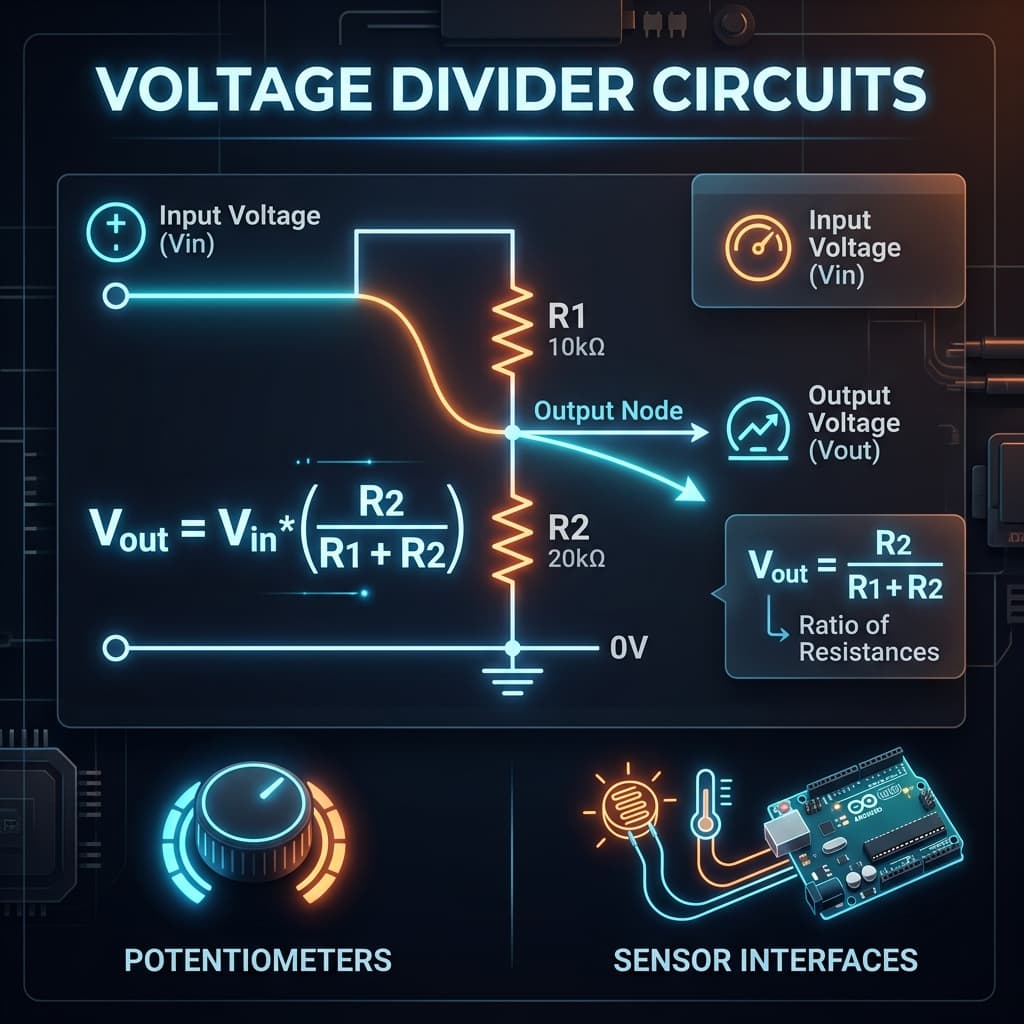
Where R1 is the top resistor (from Vin to the output node) and R2 is the bottom resistor (from the output node to ground). Vout is measured across R2.
Voltage Divider Schematic
A voltage divider consists of two resistors in series between the input voltage and ground. The output voltage is taken from the junction between R1 and R2.
Vout = Vin × R2/(R1 + R2). The output voltage is the fraction of Vin that drops across R2.
Calculate Resistors for Target Vout
Find R1 when R2 and target Vout are known.
Find R2 when R1 and target Vout are known.
Choose one resistor value and calculate the other. Then select the nearest standard resistor value for the calculated result.
Loaded Voltage Divider
When a load resistor RL is connected across R2, it acts in parallel with R2, reducing the effective bottom resistance. This lowers the output voltage compared to the unloaded case.
The load changes the effective resistance and output voltage.
For stable output, load resistance should be much larger than R2 (typically at least 10×). Otherwise, use a buffer amplifier or voltage regulator.
How to Use the Voltage Divider Calculator
- 1Choose what to calculate: output voltage, R1, R2, or loaded divider.
- 2Enter the known values with units.
- 3Click Calculate to see the result.
- 4Review the formula breakdown, divider current, and power.
Example Calculations
Basic divider
Vin = 5 V, R1 = 10 kΩ, R2 = 10 kΩ. Vout = 5 × 10k/(10k+10k) = 2.5 V.
Target 3.3 V from 5 V
Vin = 5 V, Vout = 3.3 V, R2 = 10 kΩ. R1 = 10k × (5−3.3)/3.3 ≈ 5.15 kΩ.
Loaded divider
Vin = 5 V, R1 = 10 kΩ, R2 = 10 kΩ, RL = 10 kΩ. R2' = 5 kΩ. Vout = 5 × 5k/(10k+5k) = 1.67 V instead of 2.5 V.
Divider current
Vin = 12 V, R1 = 10 kΩ, R2 = 20 kΩ. I = 12/30k = 0.4 mA.
Divider Current and Power
Divider current flows through both resistors: I = Vin/(R1 + R2). Each resistor dissipates power: P = I²R. Check power ratings in real circuits.
Common Voltage Divider Mistakes
- • Using a voltage divider to power heavy loads without a buffer or regulator.
- • Ignoring the effect of load resistance on output voltage.
- • Confusing R1 and R2 positions (R1 is on top, R2 on bottom).
- • Using very low resistor values and wasting power.
- • Using very high resistor values, making the divider noise-sensitive.
- • Forgetting resistor tolerance when precision matters.
Where Voltage Dividers Are Used
Voltage dividers are used in sensor circuits, Arduino/microcontroller analog inputs, reference voltages, battery voltage measurement, signal scaling, simple biasing circuits, physics homework, and electronics learning.
Accuracy and Limitations
This calculator assumes ideal resistors. Real resistors have tolerance and temperature coefficients. Voltage dividers are not suitable as power supplies for significant loads. For stable power output, use a voltage regulator. This tool is for educational and basic circuit calculations.
Frequently Asked Questions
What does a voltage divider calculator do?›
It calculates the output voltage from two series resistors, or helps find resistor values for a target output voltage. It also analyzes loaded dividers.
What is the voltage divider formula?›
Vout = Vin × R2/(R1 + R2). R1 is the top resistor from Vin to the output node, and R2 is the bottom resistor from the output node to ground.
How do I calculate output voltage from two resistors?›
Multiply the input voltage by the ratio of the bottom resistor to the total resistance: Vout = Vin × R2/(R1+R2).
How do I choose R1 and R2 for a target voltage?›
Fix one resistor and calculate the other. For example, R1 = R2 × (Vin − Vout)/Vout.
Why does load resistance change Vout?›
A load in parallel with R2 reduces the effective bottom resistance, changing the divider ratio and lowering the output voltage.
Can I use a voltage divider as a power supply?›
Generally no. Voltage dividers can’t maintain a stable output under significant load. Use a voltage regulator for power delivery.
What is the difference between R1 and R2?›
R1 is the top resistor (from input to output node) and R2 is the bottom resistor (from output node to ground). Vout is measured across R2.
Do resistor tolerances affect output voltage?›
Yes. A 5% tolerance on each resistor can shift the output voltage by several percent. Use tighter-tolerance resistors for precision.
How much current should a voltage divider use?›
Enough to maintain stability under load, but not so much that it wastes power. The load current should typically be much less than the divider current.
Can I use this calculator for Arduino voltage sensing?›
Yes. Voltage dividers are commonly used to scale higher voltages down to the 0–5 V or 0–3.3 V range of Arduino analog inputs.
What is the output impedance of a voltage divider?›
The output impedance (Zout) equals R1 in parallel with R2: Zout = R1×R2/(R1+R2). A lower Zout means the divider can drive loads with less voltage droop.
How do I design a low-power voltage divider for battery monitoring?›
Use high-value resistors (e.g. 1 MΩ + 1 MΩ) to minimize quiescent current. The divider current is Vin/(R1+R2). With 2 MΩ total and 3.7 V, the drain is only 1.85 µA.
Sources / References

Author & technical reviewer
Manish Kumar
PhysicsCalcs tools are reviewed with an educational focus: clear formulas, transparent assumptions, and practical context for students and science learners.
Learn more about Manish