What Is a Parallel Plate Capacitor?
A parallel-plate capacitor consists of two flat conducting plates placed parallel to each other with a dielectric material between them. When voltage is applied, opposite charges accumulate on the plates, creating a uniform electric field in the gap.
It is the simplest capacitor model and the basis for understanding all capacitors. The formula relating capacitance to geometry and material properties is fundamental in physics and engineering.
Parallel Plate Capacitor Formula
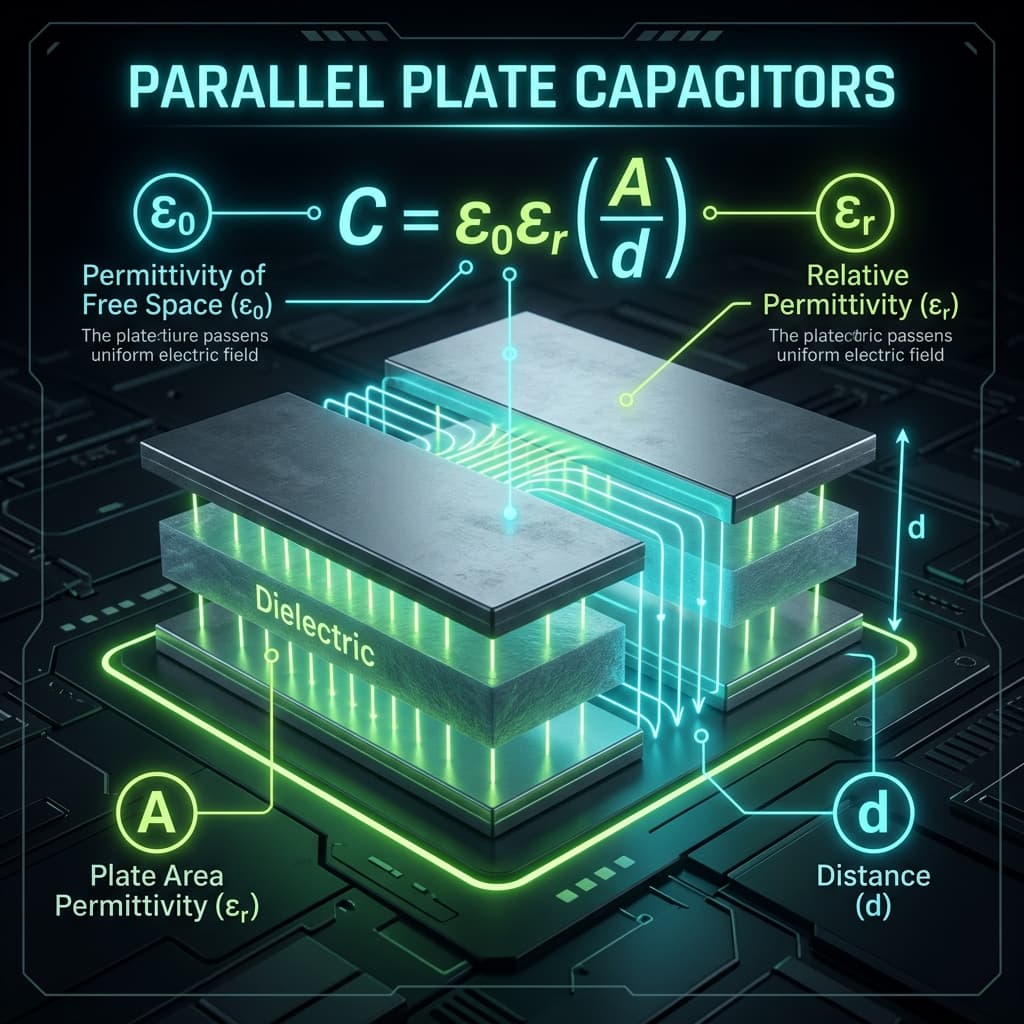
Capacitance equals relative permittivity times vacuum permittivity times plate area divided by separation.
Where εr is the dielectric constant (dimensionless), ε0 = 8.854 × 10⁻¹² F/m is the vacuum permittivity, A is the overlapping plate area (m²), and d is the plate separation (m).
Rearranged Formulas
Find area from known C, d, and εr.
Find separation from known C, A, and εr.
Find dielectric constant from known C, A, and d.
How to Use the Parallel Plate Capacitor Calculator
- 1Choose what to calculate.
- 2Select a dielectric preset or enter the relative permittivity.
- 3Enter the other known values with appropriate units.
- 4Optionally enter voltage for charge, E-field, and energy.
- 5Click Calculate and review the result.
Dielectric Materials
| Material | εr | Common Use |
|---|---|---|
| Vacuum | 1.0000 | Reference |
| Air | 1.0006 | Variable capacitors |
| PTFE | 2.1 | Low-loss RF |
| Paper | ~3 | Historic capacitors |
| Glass | ~5 | High-voltage |
| Mica | ~6 | Precision, high-Q |
| Ceramic (X7R) | ~3000 | High capacitance density |
Example Calculations
Vacuum capacitor
A = 10 cm², d = 1 mm, εr = 1. C = 1 × 8.854×10−12 × 10×10−4 / 10−3 ≈ 8.85 pF.
Mica dielectric
Same geometry, εr = 6. C = 6 × 8.85 pF = 53.1 pF.
Find area for 100 pF
C = 100 pF, d = 0.5 mm, εr = 5 (glass). A = 100×10−12 × 0.5×10−3 / (5 × 8.854×10−12) ≈ 1.13 cm².
Parallel Plate Diagram
A parallel-plate capacitor consists of two conductive plates of area A separated by distance d, with a dielectric material between them. The electric field is uniform between the plates (neglecting fringing at the edges).
Electric Field Between Plates
The electric field between ideal parallel plates is uniform and equals voltage divided by separation.
The field is directed from the positive plate to the negative plate. At the edges, the field “fringes” outward, but the ideal formula assumes infinite plates for uniform fields.
Factors Affecting Capacitance
- • Plate area: Larger area stores more charge, increasing C.
- • Plate separation: Smaller gap increases field strength, increasing C.
- • Dielectric constant: Higher εr materials reduce internal field, allowing more charge at the same voltage.
- • Temperature: Some dielectrics change εr with temperature.
- • Frequency: High-frequency fields may reduce effective εr.
Where This Calculator Is Used
Parallel-plate capacitor calculations appear in physics courses, electronics design, MEMS devices, sensor design, capacitive touchscreens, energy storage analysis, dielectric measurement, and electrical engineering fundamentals.
Dielectric Materials Comparison
The dielectric constant (εr) and breakdown strength determine a capacitor's energy density and maximum voltage. Higher εr gives more capacitance per unit area.
| Dielectric | εr | Breakdown (kV/mm) | Usage |
|---|---|---|---|
| Vacuum | 1.000 | 20–40 | Reference, physics experiments |
| Air | 1.0006 | 3 | Variable capacitors |
| PTFE (Teflon) | 2.1 | 60 | RF, microwave, low-loss |
| Polyester (PET) | 3.3 | 150 | Film capacitors (general purpose) |
| Glass | 4–10 | 10–40 | High-reliability, military |
| Aluminium oxide | 8–10 | 13 | Electrolytic capacitors |
| X7R Ceramic | 2000–4000 | 10–25 | MLCCs, decoupling |
| Y5V Ceramic | 4000–15000 | 10–20 | Highest C but worst stability |
| Barium titanate | 1200–10000 | 2–12 | Piezoelectric, ceramic caps |
Common Mistakes
- • Neglecting fringing fields — the ideal formula assumes infinite plates. When plate separation approaches plate dimensions, fringing fields increase actual capacitance beyond the calculated value.
- • Using wrong area units — area must be in m² for the formula in SI units. A common error is entering cm² without converting (1 cm² = 10²&sup4; m²).
- • Confusing absolute and relative permittivity — the formula uses εr (dimensionless) multiplied by ε0. Entering the absolute permittivity where εr is expected gives wildly wrong results.
- • Ignoring dielectric breakdown — every dielectric has a maximum electric field strength. Exceeding it causes permanent conductive paths (breakdown), destroying the capacitor.
- • Assuming εr is constant — dielectric constant varies with frequency, temperature, applied voltage, and aging. Ceramic capacitors (especially Class II) can lose over half their capacitance at rated voltage.
Accuracy and Limitations
The formula assumes infinite, perfectly parallel plates with uniform dielectric. Real capacitors have fringing fields, non-uniform dielectrics, lead inductance, and manufacturing variation. High-frequency and high-voltage effects are not modeled. This tool is for educational and introductory calculations.
Frequently Asked Questions
What is a parallel-plate capacitor?›
Two flat conducting plates separated by a dielectric. It stores energy in the electric field between the plates.
What is the formula for parallel-plate capacitance?›
C = εᵣε₀A/d, where εᵣ is relative permittivity, ε₀ is vacuum permittivity, A is plate area, and d is plate separation.
What is ε₀?›
The permittivity of free space: 8.854 × 10⁻¹² F/m. It quantifies how much electric field a vacuum permits.
What is εᵣ?›
The relative permittivity (dielectric constant) of a material. It tells how much the material increases capacitance compared to vacuum. Vacuum has εᵣ = 1.
How does area affect capacitance?›
Capacitance is proportional to plate area. Doubling the area doubles the capacitance.
How does separation affect capacitance?›
Capacitance is inversely proportional to separation. Halving the gap doubles the capacitance.
What is the electric field between the plates?›
E = V/d for ideal parallel plates. The field is uniform between the plates and directed from positive to negative.
Can I use this for non-flat geometries?›
No. The formula C = εᵣε₀A/d applies only to flat, parallel plates. Cylindrical and spherical capacitors use different formulas.
What happens if the dielectric breaks down?›
When the electric field exceeds the dielectric’s breakdown strength, current flows through the insulator, potentially damaging the capacitor.
Why are practical capacitors not simple parallel plates?›
To achieve useful capacitance in small packages, manufacturers roll or stack plates, use thin dielectrics, and choose high-εᵣ materials.
How does MLCC (multi-layer ceramic capacitor) relate to the parallel-plate formula?›
An MLCC is hundreds of parallel-plate capacitors stacked in parallel. Each layer contributes C = ε₀εᵣA/d, and the total is approximately N×(single layer C), where N is the number of active layers.
What is fringing and when does it matter?›
Fringing refers to electric field lines that bulge outward at the edges of the plates. It becomes significant when the plate separation d is comparable to the plate dimensions, increasing actual capacitance above the ideal formula prediction.
How does DC bias voltage affect ceramic capacitor value?›
Class II ceramic capacitors (X7R, X5R, Y5V) lose significant capacitance under DC bias. An X7R 10 µF/6.3 V capacitor may retain only 4–5 µF at 5 V applied. Always check the manufacturer derating curve when selecting MLCCs for power supply decoupling.
What determines the maximum voltage a parallel-plate capacitor can handle?›
The dielectric breakdown strength (kV/mm) of the insulating material. When the electric field E = V/d exceeds the breakdown threshold, the dielectric fails permanently. Voltage ratings include a safety margin, typically 50–80% of the theoretical breakdown voltage.
Sources / References

Author & technical reviewer
Manish Kumar
PhysicsCalcs tools are reviewed with an educational focus: clear formulas, transparent assumptions, and practical context for students and science learners.
Learn more about Manish