What Is Resonant Frequency?
Resonant frequency is the natural frequency at which an LC or RLC circuit oscillates with maximum energy transfer between the inductor and capacitor. At this frequency, the inductive reactance (XL) exactly equals the capacitive reactance (Xc), and they cancel each other in a series circuit.
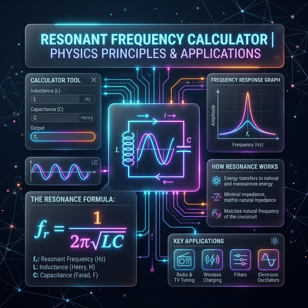
Resonance Formulas
Resonant frequency
Quality factor (series RLC)
Below, At, and Above Resonance
| Condition | Behavior | Phase |
|---|---|---|
| f < f₀ | Xc > XL → Capacitive | Current leads voltage |
| f = f₀ | XL = Xc → Resistive | In phase |
| f > f₀ | XL > Xc → Inductive | Voltage leads current |
How to Use the Resonant Frequency Calculator
- 1Choose a calculation mode.
- 2Enter inductance and/or capacitance values.
- 3For Q factor, also enter resistance.
- 4Click Calculate to see frequency, Q, bandwidth, or reactance.
- 5Review the step-by-step solution.
Example Calculations
LC Resonance
L = 10 mH, C = 100 nF. f₀ = 1/(2π√(0.01 × 10−7)) ≈ 5.03 kHz.
Find C for 1 MHz
f₀ = 1 MHz, L = 10 μH. C = 1/((2π × 10&sup6;)² × 10−5) ≈ 2.53 nF.
Where Resonant Frequency Calculations Are Used
AM/FM radio tuning, antenna design, bandpass filters, oscillators, wireless power transfer, impedance matching networks, crystal oscillators, and LC tank circuits in amplifiers.
Common Mistakes
- Confusing resonant frequency with cutoff frequency.
- Forgetting unit conversions (mH to H, nF to F).
- Using series RLC Q formula for parallel circuits.
- Assuming R affects resonant frequency.
Accuracy and Limitations
This calculator assumes ideal components. Real inductors have winding resistance and core losses, real capacitors have ESR and parasitic inductance. At very high frequencies, distributed effects and transmission-line behavior become important.
Frequently Asked Questions
What is resonant frequency?›
Resonant frequency is the frequency at which the inductive and capacitive reactances in an LC or RLC circuit are equal and cancel each other. At this frequency, energy oscillates freely between the inductor and capacitor.
Does resistance affect resonant frequency?›
No. The resonant frequency f₀ = 1/(2π√LC) depends only on inductance and capacitance. Resistance affects the Q factor, bandwidth, and damping, but not the resonant frequency itself.
What happens at resonance in a series RLC?›
At resonance, impedance is minimized and equals R. Current is maximized. The voltage across L and C can each be Q times the source voltage.
How do I choose L and C for a target frequency?›
Use f₀ = 1/(2π√LC). Pick one component, then calculate the other. This calculator’s “Find L” and “Find C” modes do this automatically.
What is the difference between resonance and cutoff frequency?›
Resonant frequency is where XL = Xc in an LC/RLC circuit. Cutoff frequency is the −3 dB point in a filter. They use different formulas and have different physical meanings.
Can I use this for parallel LC circuits?›
The formula f₀ = 1/(2π√LC) applies to both series and parallel LC circuits for the ideal case. However, the Q factor and bandwidth formulas differ for parallel RLC.
How do component tolerances affect resonant frequency?›
Standard capacitors and inductors have tolerances of ±5% to ±20%. Since f₀ = 1/(2π√LC), a worst-case combination of +10% L and +10% C shifts f₀ down by about 5%. For precision resonant circuits (crystal filters, IF stages), use components with ±1% or tighter tolerances.
What is the difference between loaded and unloaded Q?›
Unloaded Q (Qᵤ) measures the intrinsic selectivity of the LC tank with only its own losses. Loaded Q (Qᴸ) accounts for external circuit resistance coupled to the tank. Qᴸ is always lower than Qᵤ because the external load adds damping. In receiver design, Qᴸ sets the actual bandwidth.
Sources / References

Author & technical reviewer
Manish Kumar
PhysicsCalcs tools are reviewed with an educational focus: clear formulas, transparent assumptions, and practical context for students and science learners.
Learn more about Manish