What Is an RLC Circuit?
An RLC circuit contains a resistor, inductor, and capacitor. In the series configuration, all three components share the same current. The circuit exhibits frequency-dependent impedance, resonance, and can act as a bandpass or band-stop filter depending on where the output is measured.
RLC Circuit Formulas
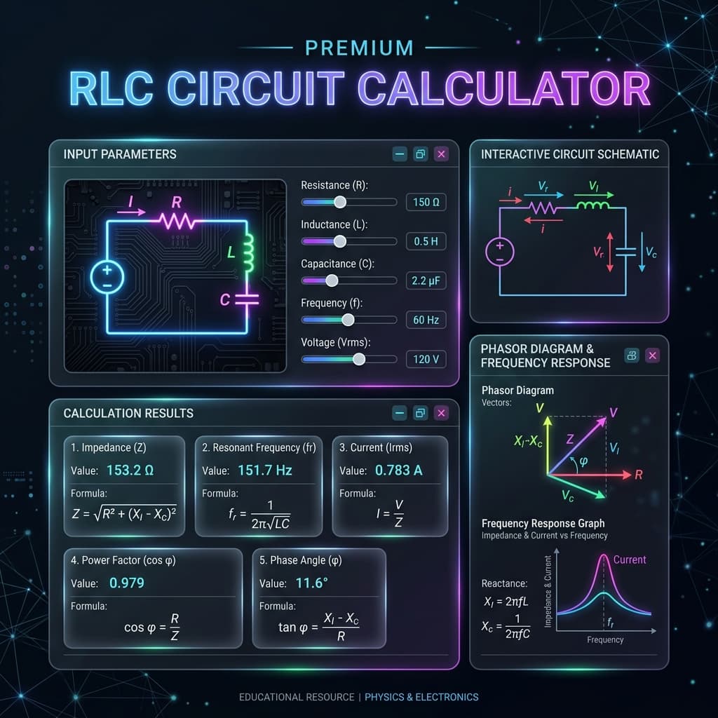
Series impedance magnitude
Resonant frequency
Quality factor
Bandwidth (−3 dB)
Resonance in RLC Circuits
At resonance, the inductive and capacitive reactances cancel (XL = Xc), leaving only resistance. This means maximum current flows, minimum impedance, and zero phase angle. The voltage across L and C can individually exceed the source voltage by a factor of Q.
Quality Factor (Q)
The Q factor describes how underdamped the circuit is. High Q (>10) means sharp resonance and narrow bandwidth, useful for radio tuning. Low Q (<1) means the circuit is overdamped with broad frequency response. Q also equals the voltage magnification factor at resonance: VL = VC = Q × Vs.
Damping Classification
The damping ratio ζ = 1/(2Q) determines how an RLC circuit responds to a step input. The three regimes are:
| Response Type | Damping Ratio (ζ) | Q Factor | Transient Behavior |
|---|---|---|---|
| Underdamped | ζ < 1 | Q > 0.5 | Oscillates with decaying amplitude before settling |
| Critically damped | ζ = 1 | Q = 0.5 | Returns to steady state in the shortest time without oscillation |
| Overdamped | ζ > 1 | Q < 0.5 | Returns slowly to steady state without oscillation |
The relationship is ζ = R/(2) × √(C/L) = 1/(2Q). Most resonant circuits (radio tuning, bandpass filters) are underdamped with Q >> 1. Critical damping (Q = 0.5) is preferred in control systems and measurement circuits where overshoot is undesirable.
How to Use the RLC Circuit Calculator
- 1Select a calculation mode from the dropdown.
- 2Enter resistance, inductance, capacitance, and/or frequency.
- 3For current mode, also enter the source voltage (RMS).
- 4Click Calculate to see impedance, phase, Q, and more.
- 5Review the step-by-step solution and explanation.
Example Calculations
Series Impedance
R = 10 Ω, L = 100 mH, C = 10 μF, f = 100 Hz. XL = 62.83 Ω, Xc = 159.15 Ω. |Z| = √(100 + 9270) ≈ 96.89 Ω. Circuit is capacitive.
Resonant Frequency
L = 100 mH, C = 10 μF. f₀ = 1/(2π√(0.1 × 10−5)) ≈ 159.15 Hz.
Q Factor
R = 10 Ω, L = 100 mH, C = 10 μF. Q = (1/10)√(0.1/10−5) = 10. BW = 159.15/10 = 15.92 Hz.
Where RLC Circuit Calculations Are Used
Radio tuning circuits, bandpass filters, antenna matching, oscillators, signal processing, power factor correction, notch filters, and educational physics and EE courses.
Common Mistakes
- Forgetting that XL and Xc subtract (not add) in series.
- Confusing series and parallel RLC formulas.
- Using peak voltage when RMS is required.
- Not converting mH to H or μF to F.
- Expecting voltage drops to add algebraically (they add as phasors).
Accuracy and Limitations
This calculator uses ideal RLC equations. Real inductors have winding resistance, real capacitors have ESR, and parasitic effects become significant at high frequencies. Mutual coupling and non-linear cores are not modeled. For precision work, use SPICE simulation.
Frequently Asked Questions
What is an RLC circuit?›
An RLC circuit contains a resistor (R), inductor (L), and capacitor (C). In a series RLC circuit, these three components are connected in one loop. The interplay of resistance, inductive reactance, and capacitive reactance determines the circuit’s frequency response.
What happens at resonance?›
At the resonant frequency, inductive reactance equals capacitive reactance (XL = Xc). The impedance drops to its minimum value R, current is maximized, and the circuit behaves as a purely resistive load.
What is the Q factor?›
The quality factor Q measures how sharp the resonance peak is. Higher Q means narrower bandwidth and greater frequency selectivity. Q = (1/R)√(L/C) for a series RLC circuit.
What is bandwidth in an RLC circuit?›
Bandwidth (BW) is the frequency range between the upper and lower −3 dB points. BW = f₀/Q. A higher Q gives a narrower bandwidth.
Can voltage across L or C exceed the source?›
Yes! At resonance in a series RLC circuit, VL and VC can each be Q times the source voltage. This voltage magnification is a key property of resonant circuits.
What is the difference between series and parallel RLC?›
In a series RLC, components share the same current and impedance is minimized at resonance. In a parallel RLC, components share the same voltage and impedance is maximized at resonance. This calculator covers series RLC.
How do I determine if a circuit is inductive or capacitive?›
If XL > Xc, the circuit is inductive (positive phase angle, voltage leads current). If Xc > XL, it is capacitive (negative phase angle, current leads voltage).
Does resistance affect resonant frequency?›
No. The resonant frequency f₀ = 1/(2π√LC) depends only on L and C. However, R affects the Q factor, bandwidth, and the sharpness of the resonance peak.
What is voltage magnification at resonance?›
In a series RLC circuit at resonance, the voltage across the inductor or capacitor individually can be Q times the source voltage. For Q = 50 with a 1 V source, VL and VC each reach 50 V. This is exploited in radio tuning circuits but requires components rated for the magnified voltage.
How do I design a bandpass filter using a series RLC circuit?›
Choose the center frequency f₀ = 1/(2π√LC) and the desired bandwidth BW = f₀/Q. Then R = (1/Q)√(L/C). Start by selecting L and C for the target f₀, then calculate R to achieve the required Q. Lower R gives higher Q (narrower bandwidth).
Sources / References

Author & technical reviewer
Manish Kumar
PhysicsCalcs tools are reviewed with an educational focus: clear formulas, transparent assumptions, and practical context for students and science learners.
Learn more about Manish