What Is an Impedance Calculator?
This calculator computes the total opposition (impedance) to alternating current in circuits with resistance and reactance. It covers series RC, RL, and RLC configurations and shows the impedance triangle, phase angle, and power factor.
Impedance Formulas
Series RC circuit.
Series RL circuit.
Series RLC circuit.
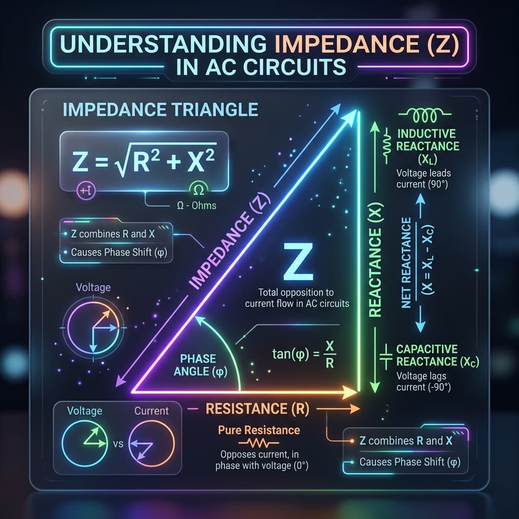
The Impedance Triangle
The impedance triangle is a right triangle with R (resistance) as the base, X (net reactance) as the vertical side, and Z (impedance) as the hypotenuse. The angle between R and Z is the phase angle φ.
Phase angle from net reactance and resistance.
Resonance in Series RLC Circuits
At resonance, XL = Xc, net reactance = 0, impedance = R.
At resonance, impedance reaches a minimum equal to R. The circuit draws maximum current for a given voltage, and the phase angle is 0°.
How to Use
- 1Choose a circuit type.
- 2Enter R, L, C, and frequency as needed.
- 3Click Calculate.
- 4Review impedance, phase, power factor, and triangle.
- 5Use AC current/voltage modes to find I or V.
Example Calculations
Series RC
R = 100 Ω, C = 1 μF, f = 1 kHz. Xc = 159.15 Ω. |Z| = √(10000+25329) ≈ 188 Ω. φ ≈ −57.9°.
Series RL
R = 100 Ω, L = 10 mH, f = 1 kHz. XL = 62.83 Ω. |Z| ≈ 118.1 Ω. φ ≈ 32.1°.
Series RLC at resonance
R = 50 Ω, L = 10 mH, C = 253.3 nF. f₀ = 1/(2π√(10−2 × 253.3×10−9)) ≈ 1 kHz. At f = 1 kHz, |Z| = 50 Ω.
Power Factor
Power factor = cos(φ) = R/|Z|. A power factor of 1 means all power is real (resistive). Lower values mean more reactive power. Capacitive circuits have leading power factor; inductive circuits have lagging power factor.
Applications
AC circuit analysis, filter design, power systems, radio circuits, transformer analysis, audio systems, impedance matching, resonant circuits, and physics homework.
Common Mistakes
- Confusing series and parallel impedance formulas.
- Adding XL and Xc instead of subtracting.
- Forgetting to convert units.
- Mixing peak and RMS values.
- Assuming ideal components at all frequencies.
Accuracy and Limitations
This calculator assumes ideal series circuits. Real components have tolerance, parasitic effects, and temperature dependence. Parallel circuits use different formulas. This tool is educational and should not replace professional circuit design.
Frequently Asked Questions
What does an impedance calculator do?›
It calculates the total opposition (impedance) to alternating current in a circuit with resistance and reactance.
What is the impedance formula?›
|Z| = √(R² + X²), where R is resistance and X is net reactance (XL − Xc for RLC).
What is the unit of impedance?›
Ohms (Ω), the same unit as resistance.
What is the impedance triangle?›
A right triangle where R is the base, X is the opposite side, and Z is the hypotenuse. The angle is the phase angle.
What is resonance in an RLC circuit?›
When XL = Xc, the net reactance is zero, impedance equals R, and phase angle is 0°.
What is the resonant frequency formula?›
f₀ = 1/(2π√(LC)).
What is power factor?›
Power factor = cos(φ) = R/|Z|. It ranges from 0 to 1, where 1 means purely resistive.
What does a negative phase angle mean?›
Current leads voltage, typical of capacitive circuits.
What does a positive phase angle mean?›
Voltage leads current, typical of inductive circuits.
Can impedance be less than resistance?›
No. Since Z = √(R² + X²), impedance is always ≥ R.
Does this work for parallel circuits?›
This calculator handles series circuits. Parallel impedance requires different formulas.
Are real circuits exactly like the calculations?›
No. Real components have tolerance, parasitic effects, and frequency-dependent behavior.
Sources / References

Author & technical reviewer
Manish Kumar
PhysicsCalcs tools are reviewed with an educational focus: clear formulas, transparent assumptions, and practical context for students and science learners.
Learn more about Manish