
What Is an RL Time Constant Calculator?
This calculator determines the time constant of an RL circuit, individual component values, and current rise or decay at any time. It includes a 1τ–5τ reference table and current curves.
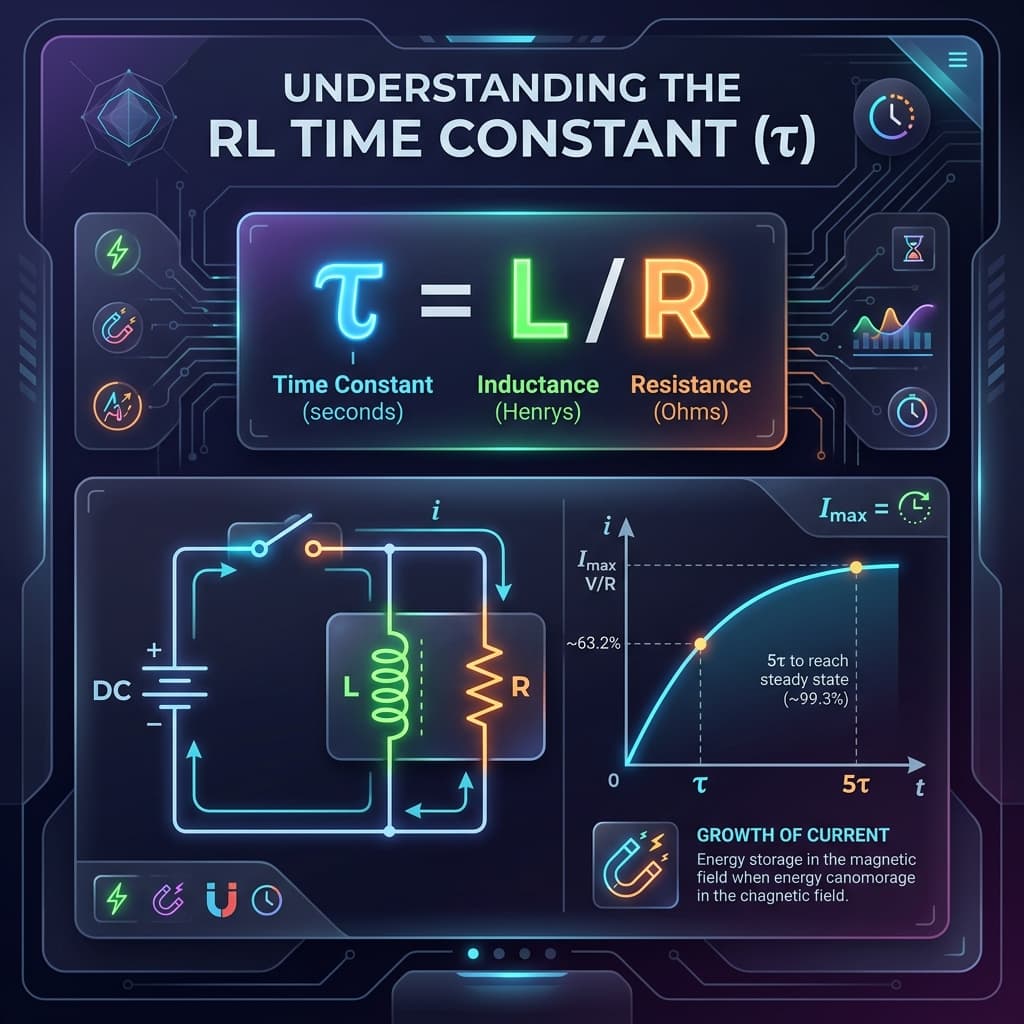
RL Time Constant Formula
Time constant in seconds. Larger L or smaller R means a slower response.
Unlike the RC time constant (τ = RC), the RL time constant decreases with increasing resistance because resistance limits how quickly the inductor’s magnetic field can build or collapse.
Current Rise Formula
Current rises from 0 toward V/R (maximum steady-state current).
Current Decay Formula
Current falls exponentially from the initial value toward 0.
1τ to 5τ Reference Table
| Time | Current Rise % | Current Decay % |
|---|---|---|
| 1τ | 63.2% | 36.8% |
| 2τ | 86.5% | 13.5% |
| 3τ | 95.0% | 5.0% |
| 4τ | 98.2% | 1.8% |
| 5τ | 99.3% | 0.7% |
How to Use
- 1Choose what to calculate.
- 2Enter L and R, or τ and one component.
- 3For current modes, enter voltage and time.
- 4Click Calculate.
- 5Review results and the τ reference table.
Examples
τ from L & R
L = 100 mH, R = 50 Ω. τ = 0.1/50 = 2 ms. 5τ = 10 ms.
Current rise at 2 ms
V = 10 V, R = 50 Ω, L = 100 mH. τ = 2 ms. At t = 2 ms (1τ): I = (10/50)(1 − e−1) ≈ 126.4 mA (63.2%).
Current decay at 4 ms
I₀ = 200 mA, τ = 2 ms. At t = 4 ms (2τ): I = 200 × e−2 ≈ 27.1 mA (13.5%).
RL vs RC Time Constants
RL and RC circuits are duals: they share the same exponential transient shape but differ in which quantity is stored, how resistance affects settling time, and what hazards arise during switching.
| Property | RC Circuit | RL Circuit |
|---|---|---|
| Time constant | τ = RC | τ = L/R |
| Energy stored in | Electric field (E = ½CV²) | Magnetic field (E = ½LI²) |
| Increasing R | Increases τ (slower) | Decreases τ (faster) |
| Charging quantity | Voltage across C rises | Current through L rises |
| Cutoff frequency | fc = 1/(2πRC) | fc = R/(2πL) |
| Switching hazard | Inrush current spike | Back-EMF voltage spike |
| Typical applications | Timing, filtering, decoupling | Relay driving, motor control, EMI filtering |
Both circuits reach 63.2% of their final value after 1τ and are considered fully settled after 5τ (99.3%). The key duality: RC stores charge on a capacitor while RL stores flux in an inductor.
Safety Notes
Interrupting current in an inductor creates large voltage spikes (back-EMF) that can damage components, cause arcing, or pose shock hazards. Always use protection circuits (flyback diodes, snubbers) and follow safety procedures when working with inductive loads.
Applications
RL circuits, switching regulators, relays, solenoids, motors, electromagnetic interference analysis, filter design, energy storage, physics homework, and electronics labs.
Common Mistakes
- Mixing RL (τ = L/R) and RC (τ = RC) formulas.
- Forgetting mH to H conversions.
- Assuming current stops instantly when power is removed.
- Ignoring winding resistance in real inductors.
- Not accounting for back-EMF during switching.
Accuracy and Limitations
This calculator assumes ideal resistors and inductors. Real components have tolerances, parasitic capacitance, core losses, and temperature dependence. Back-EMF during current interruption can be much higher than supply voltage. This tool is educational and should not replace professional circuit design or safety checks.
Frequently Asked Questions
What does an RL time constant calculator do?›
It calculates the RL time constant, current rise, current decay, and related values for a resistor-inductor circuit.
What is the RL time constant formula?›
τ = L/R, where L is inductance in henries and R is resistance in ohms.
What is the unit of the RL time constant?›
Seconds (s). Common values are in μs, ms, or s.
How does current rise in an RL circuit?›
I(t) = (V/R)(1 − e^(−tR/L)). Current rises exponentially toward V/R.
How does current decay in an RL circuit?›
I(t) = I₀ e^(−tR/L). Current falls exponentially toward zero.
How long does current take to reach steady state?›
Approximately 5τ to reach about 99.3% of the final value.
What does a larger inductance do to the time constant?›
Larger L increases τ, making current changes slower.
What does a larger resistance do to the time constant?›
Larger R decreases τ, making current changes faster.
How is the RL time constant different from RC?›
RC: τ = RC (increases with R). RL: τ = L/R (decreases with R). They use different energy storage components.
Can I find R or L from a known τ?›
Yes. R = L/τ or L = τ × R.
Why are RL circuits potentially dangerous?›
Interrupting current in an inductor produces large back-EMF voltage spikes.
Are real RL circuits ideal?›
No. Real inductors have winding resistance, parasitic capacitance, and core losses that affect behavior.
Why can interrupting an inductive circuit cause voltage spikes?›
An inductor resists changes in current. When current is suddenly interrupted, the inductor generates a large back-EMF (V = −L di/dt) to try to maintain current flow. This spike can be hundreds or thousands of volts, potentially damaging switches and semiconductors. Flyback diodes or snubber circuits are used for protection.
How does winding resistance affect the RL time constant?›
Real inductors have DC winding resistance (DCR) that adds to the external resistance R. The effective time constant is τ = L/(R + R_DCR). For large inductors with significant DCR, ignoring it leads to overestimating the time constant.
Sources / References

Author & technical reviewer
Manish Kumar
PhysicsCalcs tools are reviewed with an educational focus: clear formulas, transparent assumptions, and practical context for students and science learners.
Learn more about Manish