What Is an RC Circuit?
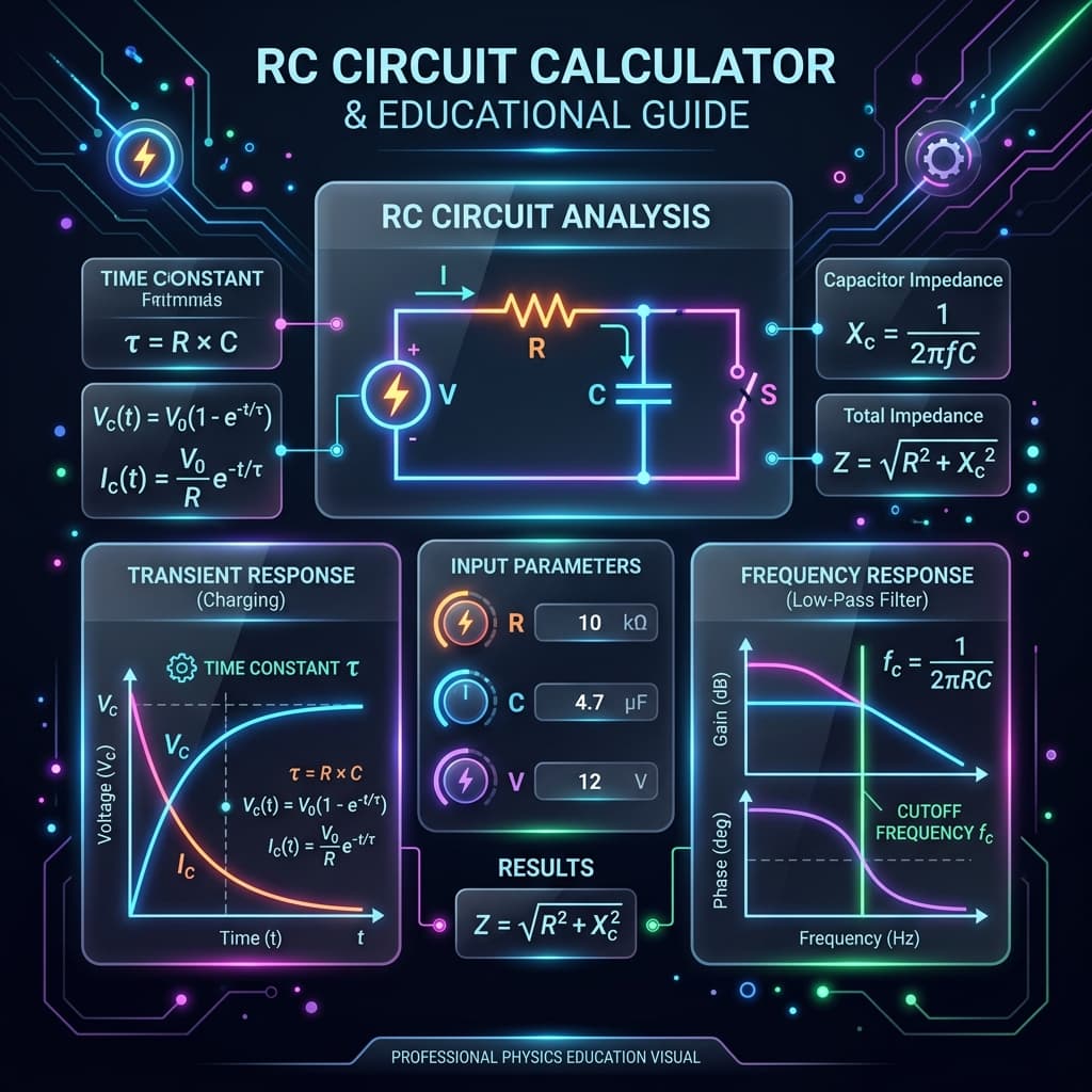
An RC circuit is a fundamental electrical circuit consisting of a resistor (R) and a capacitor (C). It is the building block for timing circuits, filters, coupling networks, and signal processing. The interaction between resistance and capacitance creates exponential charging/discharging behavior and frequency-dependent filtering.
How is this different from other RC tools? The RC Time Constant Calculator focuses on finding τ and component values. The Capacitor Charge Calculator gives detailed transient analysis. This tool combines both transient and filter analysis in one place.
Core RC Circuit Formulas
Time constant in seconds
Cutoff frequency (−3 dB point)
Charging voltage
Discharging voltage
RC Transient Behavior
When a voltage is applied to an RC circuit, the capacitor charges exponentially. The time constant τ = RC determines the speed: larger τ means slower charging. During charging, current starts at Vs/R and decays to zero. During discharging, the capacitor releases stored energy through the resistor.
| Time | Charged % | Remaining % |
|---|---|---|
| 1τ | 63.2% | 36.8% |
| 2τ | 86.5% | 13.5% |
| 3τ | 95.0% | 5.0% |
| 4τ | 98.2% | 1.8% |
| 5τ | 99.3% | 0.7% |
RC Filters: Low-Pass and High-Pass
The same RC circuit can act as a frequency filter. The cutoff frequency fc = 1/(2πRC) is the −3 dB point where output power is halved.
| Feature | Low-Pass | High-Pass |
|---|---|---|
| Output across | Capacitor | Resistor |
| Passes | Low frequencies | High frequencies |
| Attenuates | High frequencies | Low frequencies |
| Rolloff | −20 dB/decade | +20 dB/decade |
How to Use the RC Circuit Calculator
- 1Select a calculation mode (time constant, charging, discharging, time-to-target, or filter).
- 2Enter resistance and capacitance values with appropriate units.
- 3For transient modes, add supply voltage and time. For filter modes, add signal frequency.
- 4Click Calculate to see results with formulas and explanations.
- 5Use Quick Fill presets for common RC combinations.
Example Calculations
Time Constant
R = 10 kΩ, C = 100 μF. τ = 10,000 × 0.0001 = 1 second. fc = 1/(2π × 1) ≈ 0.159 Hz.
Charging Voltage at 2τ
R = 1 kΩ, C = 1 μF, Vs = 5 V, t = 2 ms (2τ). Vc = 5(1 − e−2) ≈ 4.32 V (86.5%).
Low-Pass Filter
R = 1 kΩ, C = 0.1 μF. fc = 1/(2π × 1000 × 10−7) ≈ 1.59 kHz. At 10 kHz, gain ≈ −16.1 dB.
Where RC Circuit Calculations Are Used
Timer circuits (555 timer, monostable), audio tone controls, anti-aliasing filters, sensor signal conditioning, coupling/decoupling networks, power supply ripple filtering, oscilloscope probe compensation, PWM to analog conversion, and debouncing circuits.
Common Mistakes
- Confusing charging and discharging formulas.
- Forgetting to convert kΩ to Ω or μF to F before calculating.
- Assuming the capacitor is fully charged before 5τ.
- Mixing up low-pass and high-pass output nodes.
- Using peak voltage instead of RMS for filter calculations.
- Ignoring ESR of real capacitors in high-frequency filter designs.
Accuracy and Limitations
This calculator uses ideal RC circuit equations. Real-world factors include capacitor ESR, tolerance (typically ±10–20%), temperature coefficients, dielectric absorption, and parasitic inductance at high frequencies. For critical designs, use SPICE simulation and verify with measurements.
Frequently Asked Questions
What is an RC circuit?›
An RC circuit contains a resistor (R) and capacitor (C) connected in series or parallel. It is one of the most fundamental circuits in electronics, used for timing, filtering, and signal conditioning.
What is the RC time constant?›
The time constant τ = RC is the time it takes for the capacitor voltage to reach about 63.2% of its final value during charging, or drop to 36.8% during discharging.
How long does it take to fully charge a capacitor?›
Theoretically a capacitor never fully charges, but after 5τ it reaches 99.3% of the supply voltage, which is considered fully charged for practical purposes.
What is an RC low-pass filter?›
When the output is taken across the capacitor, the RC circuit passes low frequencies and attenuates high frequencies, with a −3 dB cutoff at fc = 1/(2πRC).
What is an RC high-pass filter?›
When the output is taken across the resistor, the RC circuit passes high frequencies and attenuates low frequencies, with the same cutoff frequency fc = 1/(2πRC).
How is this different from the RC Time Constant Calculator?›
The RC Time Constant Calculator focuses on finding τ, cutoff frequency, and component values. This RC Circuit Calculator adds full transient analysis (charging/discharging at any time) and filter modes (gain, phase, output voltage at any frequency).
Can I use this for RL circuits?›
No, this tool is specifically for RC circuits. Use the RL Time Constant Calculator for inductor-resistor circuits.
Does filter rolloff slope matter?›
A first-order RC filter rolls off at −20 dB/decade (or −6 dB/octave). For steeper rolloff, you need higher-order filters with multiple stages.
What units should I use?›
You can use any supported units — the calculator converts automatically. Common pairs: kΩ with μF, Ω with mF, or MΩ with pF.
Is this accurate for real components?›
The calculator uses ideal formulas. Real components have tolerances, ESR, parasitic inductance, and temperature effects that may cause small deviations.
How do I cascade two RC filter stages for steeper rolloff?›
Two identical RC stages in series give −40 dB/decade rolloff instead of −20 dB/decade. However, the second stage loads the first, shifting the effective cutoff. Use a buffer (op-amp voltage follower) between stages to maintain the designed cutoff frequency.
Can I use this calculator for AC coupling capacitor selection?›
Yes. For AC coupling, the RC high-pass mode shows the −3 dB frequency. Choose C so that fc is well below your signal frequency. A common rule: fc should be at least 10× lower than the lowest signal frequency to keep signal attenuation below 0.05 dB.
Sources / References

Author & technical reviewer
Manish Kumar
PhysicsCalcs tools are reviewed with an educational focus: clear formulas, transparent assumptions, and practical context for students and science learners.
Learn more about Manish